 | |||||||||||||
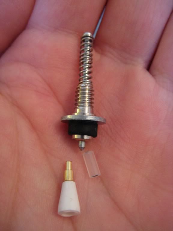
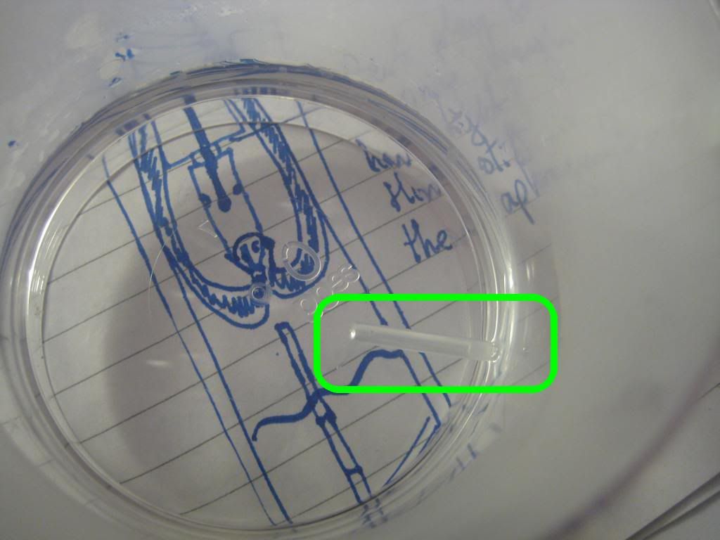
| Below the filler housing - the protruding end of the plunger rod, clear tube connector, golden ballpoint tip, and pellet holder. |
The plunger rod's job is to keep ahold of the rubber diaphragm within the barrel, and give it a good push and pull. A ballpoint pen makes very light work out of the real hurdle in making a lowly 616 vacumatic when it has no business being so; how to make this plunger rod grip the diaphragm.
I had read David Armstrong's excellent Haynes-style dismantling of a real Parker vacumatic filler unit with great interest, gaining a much clearer understanding of how this could be accomplished. In every vacumatic diaphragm, there is a small rigid pellet, housed in a wee pocket at the top. In a real Parker vacumatic, this rigid area gives the mechanism something to hold onto. A dedicated, precisely sized pellet holder glued to the bottom end of the plunger rod does the job.
The inspiration to look at ballpoints for this task came from an old FPN post of PenFisher's, on making spare pellet holders for use in genuine Parker vacumatic filler units. This involved cutting out a cross section from a tapered Papermate Writebros ballpoint pen. For my purposes, the British Red Cross freebie ballpoint's design makes it even easier still, as the only cut you need to make is across a straight ridge. It could have been made with this conversion in mind, it's that perfect (I like to think this was a purposeful subversion by some shadowy cabal of renegade designers). Here's a short video, showing a test of the pellet holder's strength. It actually compresses the plunger return spring before letting go of the diaphragm.
As all the parts here discussed came from the same ballpoint, they all snap together securely. The pellet holder clicks into the metal tip of the ballpoint, which clicks into a short length of the rigid ballpoint ink tube. When heated in boiling water, the tube softens enough to have the steel blind rivet tang driven into it. After cooling, they are so strongly connected that it takes two sets of pliers to separate them!
To break that fevered gibbering down into a coherent build sequence, I'll start with the ballpoint pen in hand.
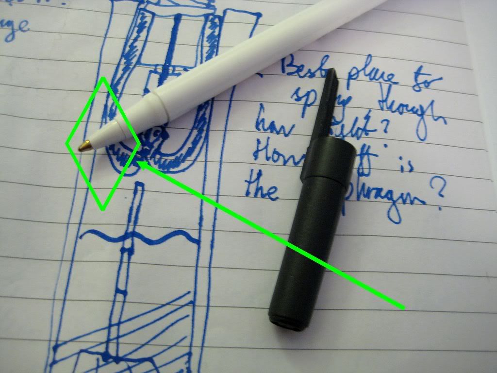 | ||||||||
| A mailshot British Red Cross ballpoint pen. The area highlighted in green became the pellet holder. |
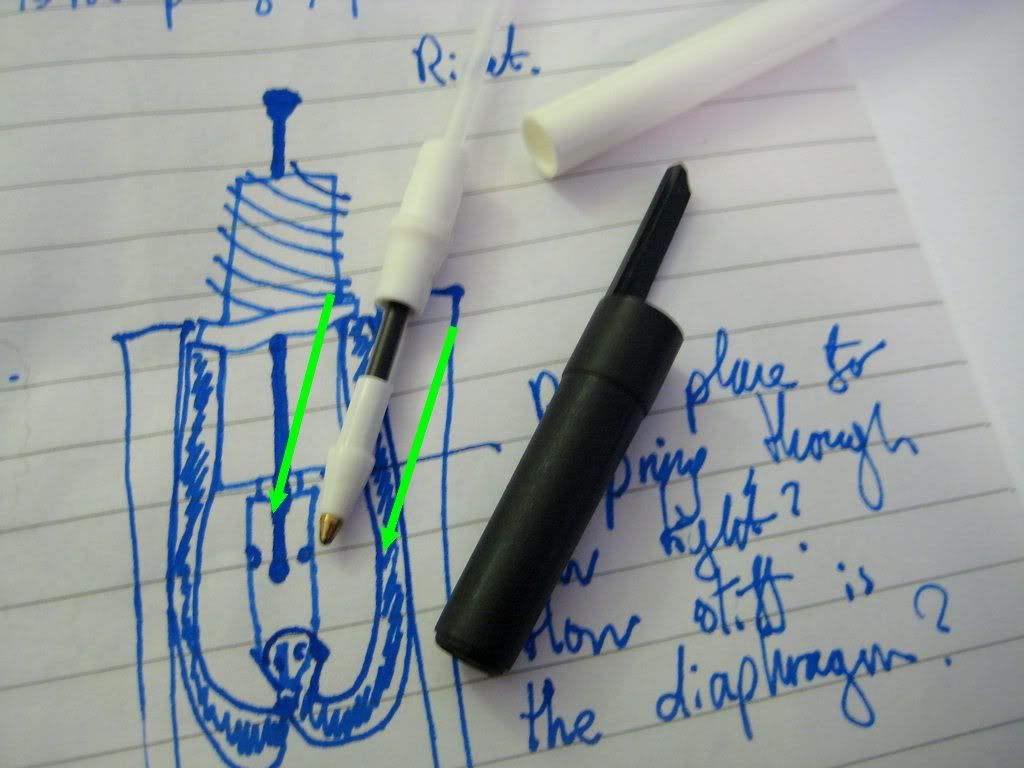 |
| Pulling the ballpoint pen apart. Notice how little ink the tube is actually filled with. Good to see the Red Cross aren't wasting too much cash on this sort of thing. |
The golden metal ballpoint tip needs to be taken out, and reinstalled the other way around - as shown in this post's first photograph. It is easiest to push it against a hard surface, straight into the plastic surround - it will drop out the other end. Then cut off the end off the plastic piece, straight across the ridge highlighted in orange.
 |
| To release the tip, press it into the plastic surround. |
 | ||
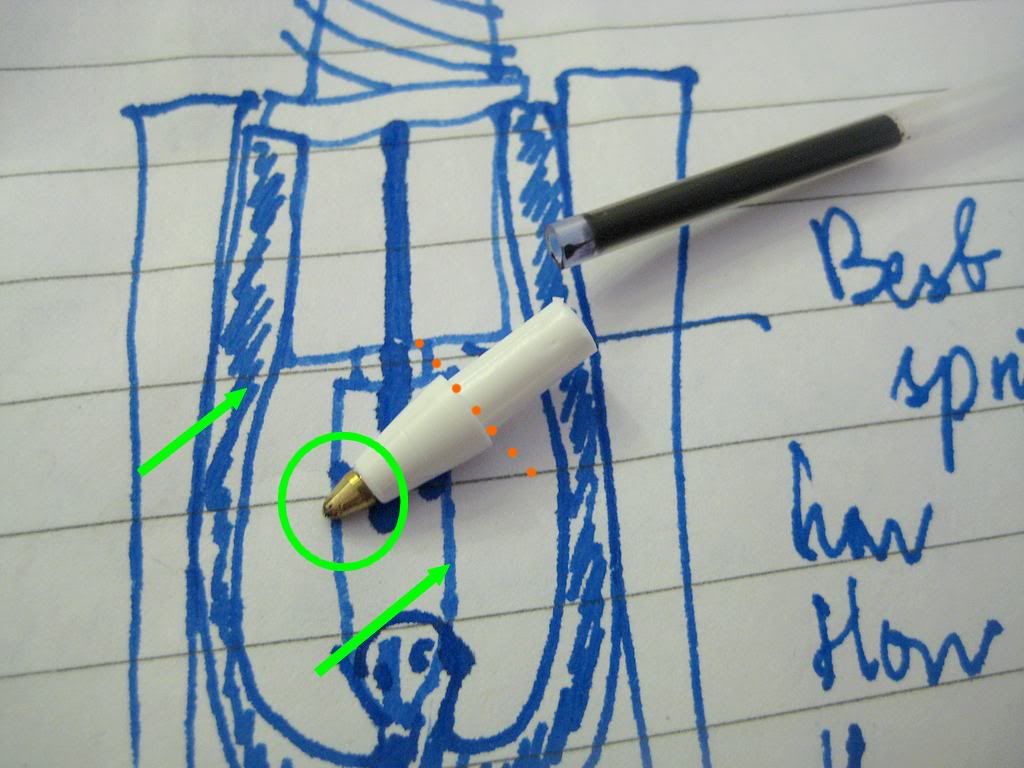
| Reinsert the tip the opposite way around - it will still click into place. Then cut along the orange line to discard the excess plastic. |
 |
| Heating a length of the ballpoint's ink tube (highlighted) in boiling water. |
First of all, the rod wants shortening, to minimise wasted barrel space. Secondly, grinding the end to a point greatly helps drive the steel plunger rod into the clear plastic tube.
|
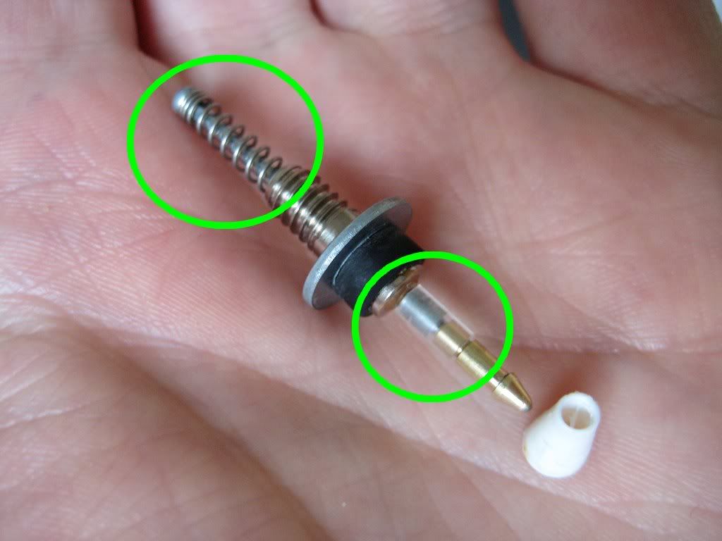
| The exposed end of the steel plunger rod, ready to be driven into the clear plastic tube. |
It's best to put off attaching the pellet holder until after the plunger rod is forced into the plastic tube, to avoid stressing it unnecessarily. Both the exposed end of the plunger rod and the clear connecting tube were cut as short as possible - after all, the less barrel space the filler takes up, the greater the pen's ink capacity.
 |
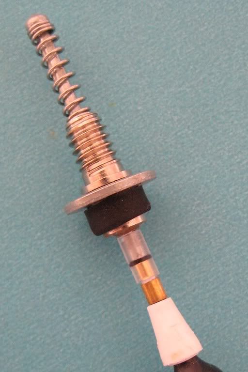
| The plunger rod secured to the ink tube, which acts as a physical stop as well as a connection to the pellet holder. |
 |
| The complete 616 Jumbo vacumatic filler, ready for its diaphragm. |
No comments:
Post a Comment
Comments seem to be working okay again. You can try leaving one, it might work! If not, you can reach me on twitter if you like @Flounder_FPN