To see one working in action answered a lot of questions - it seemed that button filling is almost the antithesis of the long stroke, low internal stress touchdown system I first encountered many posts ago. A very short downward movement of the button pushes a lot of tension through the sprung steel strip. This steel deforms, pushes against the rigid barrel wall, and is forced to bow outward, compressing the flexible ink sack.
Pausing at 20 seconds in, my attention was held by the main stress points on one side of the plastic barrel - near the top and bottom of the ink sac, and, I suppose, below the ink sac where the end of the pressure bar sits. The thickness of that demonstrator's barrel plastic is easily thrice, maybe quadruple the Hero's, most likely to withstand stresses from the pressure bar flexing against it.
Main alterations to the steel cage
With this in mind, I turned my attention to the 616's factory squeeze filler cage assembly. This is a simple tapered metal tube with a piece of bent steel inserted to squeeze the ink sac using finger pressure.
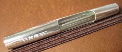
It struck me that if the pressure bar worked against the steel wall of this cage rather than the weak plastic wall of the outer barrel, the pen would cope with the rigours of use far better. If the bottom end of the pressure bar was also hinged on the steel cage rather than dug into the plastic section near the sac nipple, then pretty much all the stress forces from using the pressure bar filler would be held internally within this steel cage.
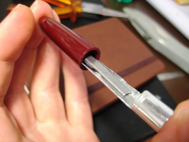
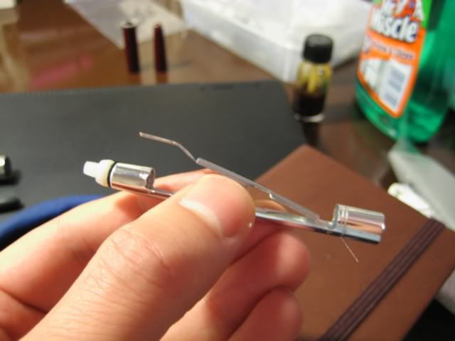
A picture says a thousand words, so here's 2000 words of exposition. This is the modified cage; the pressure bar is at idle, and the blind cap press button attached for this demonstration.
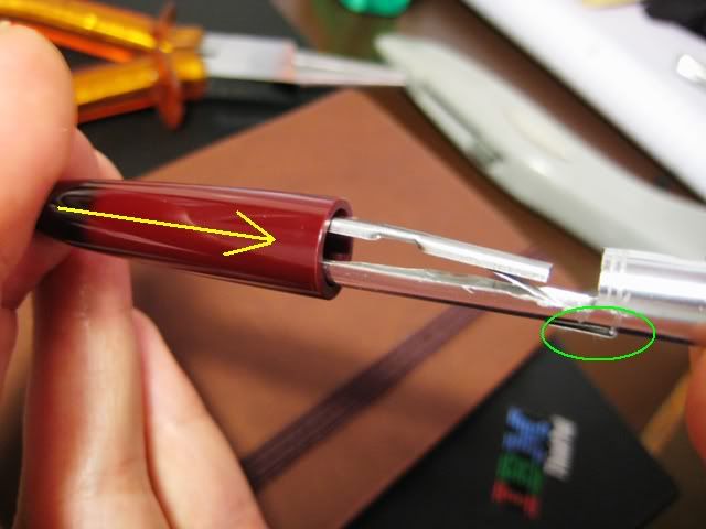
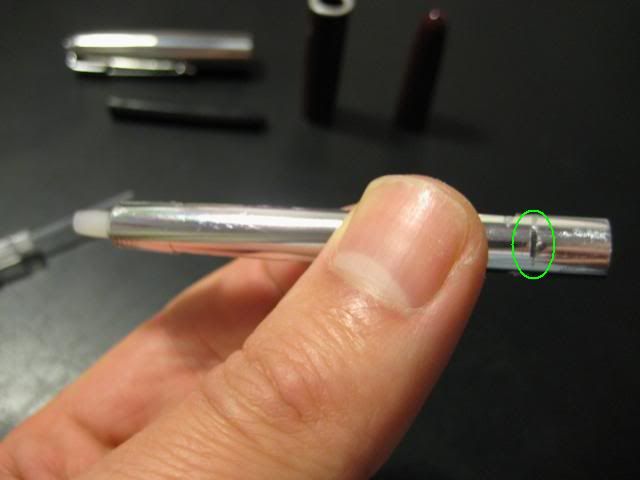
Now here's the pressure bar extended as the blind cap is pressed (in the direction of the yellow arrow). The bottom end of the pressure bar is held captive within the cage by a tight fold, which was made through a thin slot cut in the cage wall (circled in green). To see it in operation, I was surprised by the short distance the blind cap had travelled to fully extend the pressure bar into the sac cavity.
The sac cavity is unnecessarily large - this was before I used the new latex ink sac. I cut progressively more and more away from the steel cage to make it fit both the new pressure bar and the old silicon sac (I had the idea in my head that it wouldn't budge because it wanted more space to deform). If I try this again - and I'm quite tempted to - I would leave more of the old squeeze filler cage intact, at least a loop in the middle.
Still, there it is. First, I used pliers to pull out the original bent steel squeeze bar, and then, using the small cutting attachment on the mini drill, extended the original cavity to the size in the photo below. A hole was made in the top of the cage to accommodate the M4 nylon screw's shaft, which is fitted upside down - more on that below.
 The Taming of the Screw
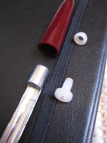
A conventional blind cap has threads cut or molded into the plastic, to screw it on and off the barrel of the pen. Without a tap and die set, and being unable to find a suitable threaded insert as an alternative, the orthodox approach was out of the question.
This is where the nylon M4 screw and nut come in - the nut is glued inside the blind cap, while the screw is lodged upside down at the top of the modified cage. They solve two problems very nicely - how to make the blind cap screw on and off, and how to trigger the pressure bar. Deep breath:
- The screw itself does not rotate. The top end of the pressure bar (which, remember, is held captive in the metal cage) is lodged in the screw head slot, preventing any rotation.
- So in this case, the blind cap screws on and off the barrel via the nut glued inside it, which revolves around the unspinnable screw.
- The screw's head is wider than the hole cut to accommodate the screw's shaft, and so acts as a physical stop, preventing the screw from being pulled out from the top. This is a very clunky way of saying the only movement the screw can make is in a limited range, straight up and down. In turn, that's a clunky way of saying when the screw is pushed down, the pressure bar squeezes the ink sac.
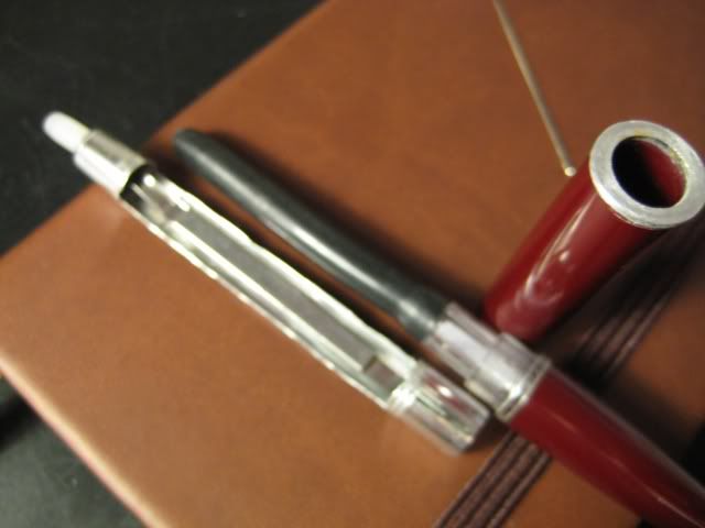
- In the pressure bar on the left, notice the gap (circled) between the sprung steel and the sac pressing part. This is no good. I tried to fix it myself instead of sending it back, mangled it, and had to get a new one.
I went for nylon rather than steel parts so they could be shaped to fit the blind cap and sac cage easily. The head of the M4 screw below needs to be made smaller to fit in the cage, while the nut needs to shaped into a cone to better fit the inner walls of the blind cap.
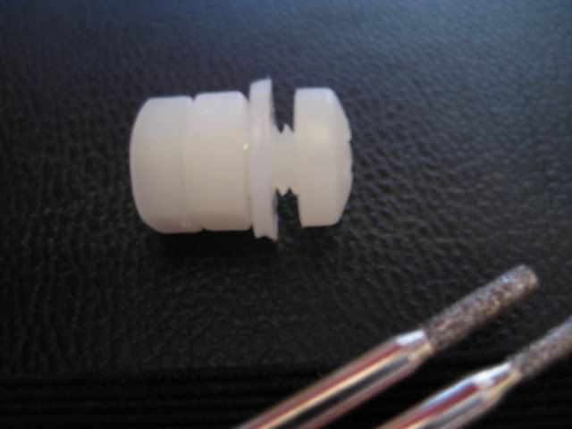
Shaping the Blind Cap Nut
All this required was grinding down to make it a little thinner, and then making it cone shaped. I just secured it in the mandrel of the mini drill, and held it at a steady angle against sandpaper. I used an offcut from the sac to make the little gasket two photos above.
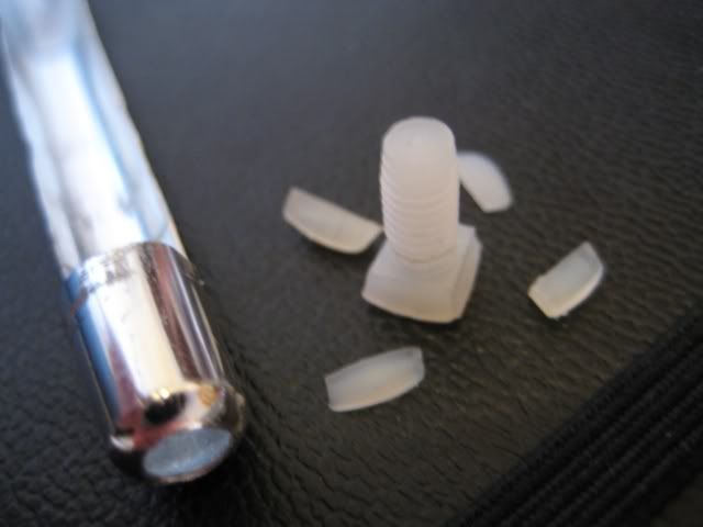
Shaping the Screw/Button
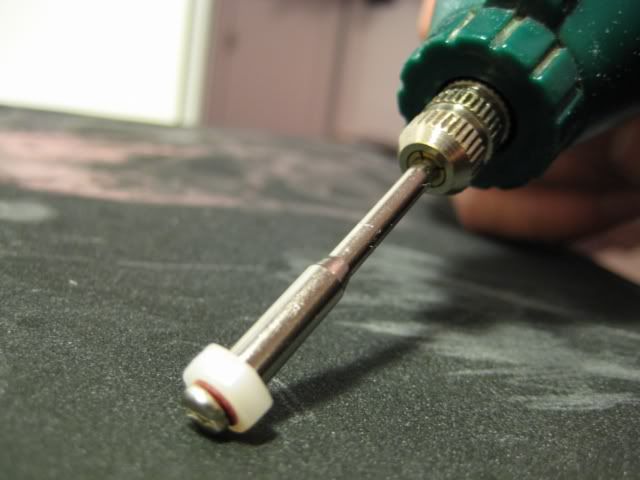
To lend a smooth action to depressing the screw, I ground off the first few threads. The rest were protected by a washer and two nuts from the 10 pack.
Then I cut the screw's head down to size, and sanded the outer edges smooth.
Final Alteration to the Cage, Installing the Pressure Bar
With the nylon screw ready, the pressure bar could be installed. I cut a slot in the cage (circled) just above where the sac attaches to the nipple. Then I held the pressure bar in place - tight against the screw - and scratched a mark on it through the slot, as an indicator of where to make the fold.
Then I put the screw inside the cage, lined up its head ready to slot in the top of the pressure bar, and tightened the blind cap nut over it. I shoved a little bluetack in the slot to make feeding the pressure bar in the right place easier.
Almost done:
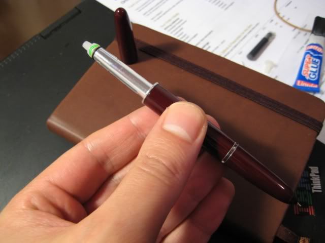
With the pressure bar installed, the cage was ready to be fitted to the pen. Terrible photo, eh? I've superglued the trim ring (the only thing in focus) onto the barrel in this photograph.
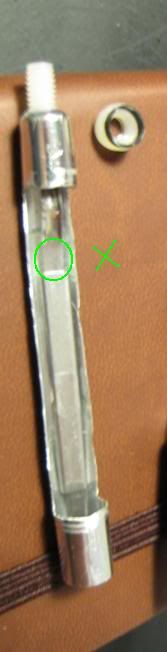
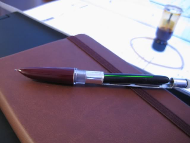
I positioned the cage so that the pressure bar was directly opposite the breather tube (MSPaint x-rayed in green). This way, the pressure bar would not have to fight the stiff breather tube to squeeze the ink sac, and I wanted to avoid stressing the breather tube anyway.
Final assembly of the blind cap and nut
The final step was to glue the blind cap to the nut. To ensure it lined up properly, I left the nut on the screw, applied superglue to the area highlighted in green, and held the blind cap tightly against the barrel for about 5 minutes. Then I let it set for about an hour before use, to give the glue time to bond properly.
I uploaded a short demonstration clip of this 616 in use to YouTube, embedded in the next post.
No comments:
Post a Comment
Comments seem to be working okay again. You can try leaving one, it might work! If not, you can reach me on twitter if you like @Flounder_FPN